[Wotian sharing] Two-wire temperature transmitter
From: Issued date 2020.02.06 Back
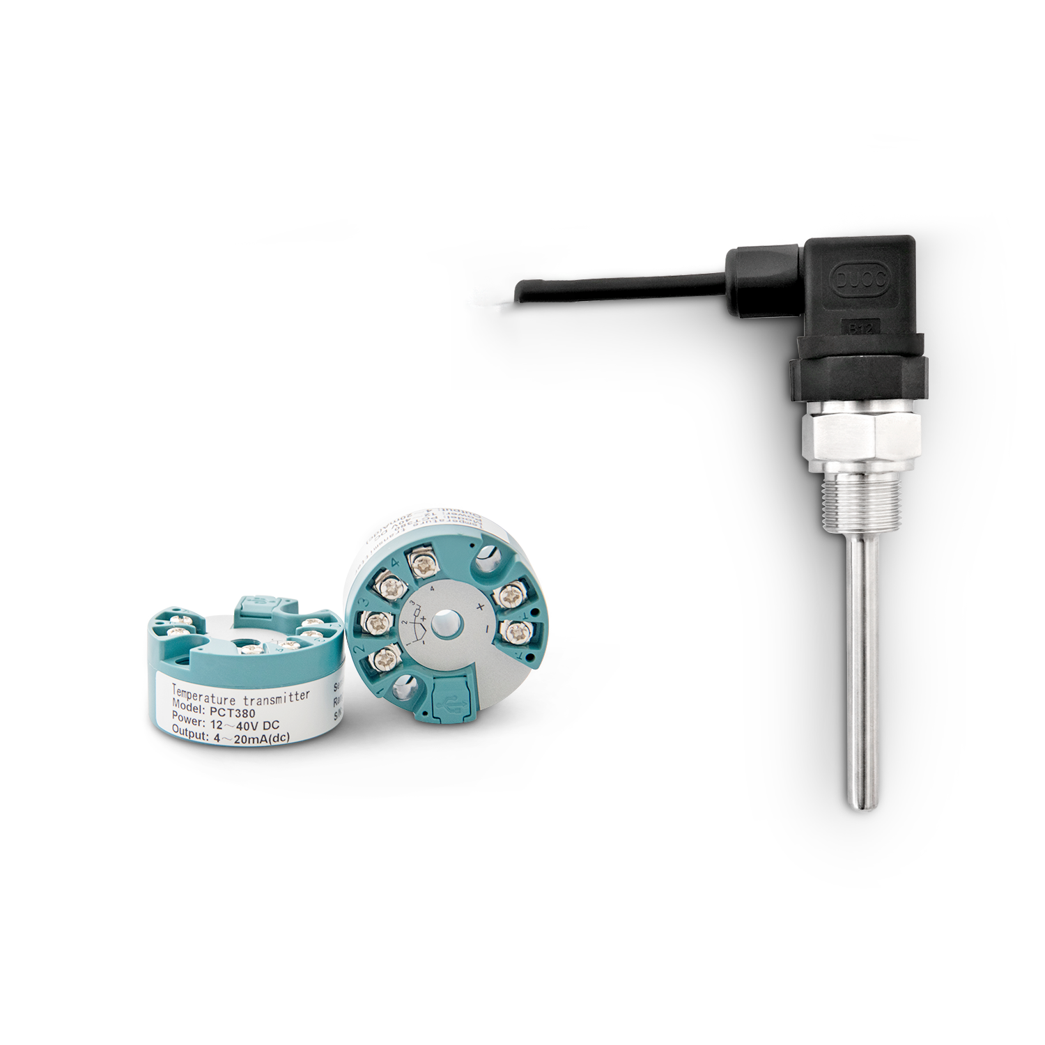
Two-wire temperature transmitters are widely used in modern industrial measurement and control systems. The transmitter can be combined with a thermal resistor and a thermocouple to linearly convert the temperature signal into a 4-20mA DC standard output current signal and modulate it on two power lines. The remote object under test is connected to the transmitter installed in the sensor junction box via the power cord. The transmitter has a universal input negative line structure, but the circuit parameters of its range processing unit vary with the sensor type and measurement range. Changes, the actual application needs to adjust the relevant parameters based on experience, and the adjustment work is very tedious, so it is necessary to use software to simplify the adjustment work, the theoretical analysis and formula derivation of the actual circuit is imperative.
Analysis of thermal resistance two-wire transmitter
The current I transmitted on the power line (4-20mA, of which 4mA is the static working current). In order to simplify the analysis, the current (0-16mA) can be used as the analysis object, and the op amp is regarded as an ideal op amp. The functional modules of the circuit are mainly Includes four parts: signal acquisition, stage amplification and linearization, zero adjustment and secondary amplification and full adjustment, and V / I module.
Analysis of thermocouple two-wire transmitter
The thermocouple transmitter circuit is similar to the thermal resistance transmitter, with the main differences being cold junction compensation and linearization circuits. Cold junction compensation is relatively simple, and the linearization circuit is more complicated and has the most characteristics. The following only analyzes the linearization circuit.
The method of linearizing the thermocouple is based on the linear relationship between the thermocouple's own voltage and temperature. The input voltage of the op amp and the output current are fitted into a number of linear segments, and the nonlinear relationship between the voltage and temperature of the thermocouple itself is approximated. The output current and temperature are approximately linear. The core of linear adjustment is to change the magnification of the op amp piece by piece to make it a piece of straight line. The specific method is to make the broken-line parallel branches composed of diode compensation resistors continue to function in different positions of the input signal.
According to the analysis results of the thermal resistance and thermocouple transmitter circuits, corresponding auxiliary software can be made to simplify the process of adjusting the circuit-related parameters when the sensor type and temperature range are changed. The analysis formula can be used in the software to calculate each output Value, and then gradually change related circuit parameters such as linearization adjustment resistance, amplification adjustment resistance and zero adjustment, full resistance, etc., so that the output current I, meet the linear output of 4-20mA, to achieve different measurement conditions, quickly determine the function of the circuit parameter.

